The DMP Programmer's Manual
The Digital Motion Processor in the InvenSense MPU-6050 family (MPU-6050, MPU-6500, MPU-9150, MPU-9250) and, as DMP3, in the ICM-20948: its architecture, memory, instruction set, host interface and assembly language.
Project maintained by jabezwinston Hosted on GitHub Pages — Theme by mattgraham
2. Memory Organization and Data Types
2.1 One Memory for Code and Data
The DMP has a single memory. Code and data share it, and the program can store over its own code. There is no ROM or flash: the host writes the program and its data before it starts the DMP (Chapter 7).
- Volatility. The memory keeps its contents across a device reset (
PWR_MGMT_1= 0x80) and across DMP_RST, and loses them at power-off. On the ICM-20948 a device reset writes 8 bytes of part-specific data at 0x0080–0x0087, so load the program after the reset. - Byte order. Big-endian: the byte at the lowest address is the most significant.
- Words. Every arithmetic operand is a 32-bit word on a 4-byte boundary.
| MPU-6050 | ICM-20948 | |
|---|---|---|
| DMP memory | 3 KB, 0x000–0xBFF | 16 KB, 0x0000–0x3FFF |
| reachable by a pointer | all of it, through the block field | 0x0000–0x0FFF |
| FIFO | 1024 B, outside DMP memory | 4096 B, DMP memory 0x3000–0x3FFF |
| sample page | 0x000–0x00D | 0x0000–0x0011 |
| default entry point | 0x400 | 0x1000 |
2.2 MPU-6050 Memory Map
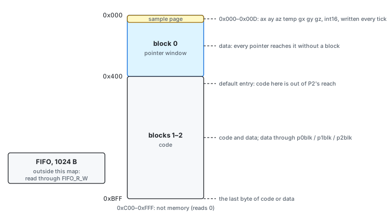
Figure 2-1. MPU-6050 DMP memory map
| Address | Contents |
|---|---|
| 0x000–0x00D | The sample page (§2.4), rewritten by the hardware at every sample tick. |
| 0x00E–0x3FF | Data. Every pointer reaches block 0 without the block field. |
| 0x400–0xBFF | Code, from the default entry point 0x400. Pointers reach this region only through the block field, so stores cannot overwrite code placed here by accident. |
| 0xC00–0xFFF | Not memory. Host reads return 0. |
Code may start anywhere in 0x00E–0xBFF. Execution runs straight through the address space from
the entry point, and the last byte of code may be 0xBFF. A program must reach end before 0xBFF.
2.3 ICM-20948 Memory Map
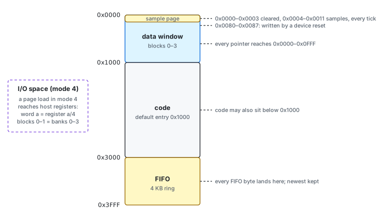
Figure 2-2. ICM-20948 DMP memory map
| Address | Contents |
|---|---|
| 0x0000–0x0003 | Cleared by the hardware at every sample tick. |
| 0x0004–0x0011 | The sample page (§2.4), rewritten at every sample tick. |
| 0x0080–0x0087 | Written with part data by a device reset. Ordinary memory otherwise. |
| 0x0000–0x0FFF | The data window: every pointer reaches it (blocks 0–3). |
| 0x1000–0x2FFF | Code, from the default entry point 0x1000. Code may also be placed in the data window. |
| 0x3000–0x3FFF | The FIFO, a 4 KB ring. Every byte the program emits lands here, and the host reads it through FIFO_R_W. Code and data must end below 0x3000. |
The I/O space. In mode 4 (§3.8), a page load (p0page, p1page, p2page) points the pointer
into the host’s register file instead of memory. Word a of that space is register a / 4. The
four register banks lie end to end, 128 registers each, so blocks 0–1 cover banks 0–3, and blocks
2–3 reach nothing.
- A read returns the register in the low byte of the word.
- A store writes the register.
- Configuration and trim registers read back. Live sensor outputs,
PWR_MGMT_1,INT_ENABLEand a few others read 0.
A MOV whose pointers were loaded before mode 4 is an ordinary memory MOV. The sample page is memory, not I/O.
2.4 The Sample Page
Before each pass, and at every sample tick, the hardware writes the latest sensor sample into the sample page. Each value is a 16-bit two’s-complement count, big-endian, as the host’s own output registers hold it.
| Offset | MPU-6050 (0x000) | ICM-20948 (0x0000) |
|---|---|---|
| +0x00 | accel X | 0 (cleared) |
| +0x02 | accel Y | 0 (cleared) |
| +0x04 | accel Z | accel X |
| +0x06 | temperature | accel Y |
| +0x08 | gyro X | accel Z |
| +0x0A | gyro Y | gyro X |
| +0x0C | gyro Z | gyro Y |
| +0x0E | not written | gyro Z |
| +0x10 | — | temperature |
- FSYNC. With
EXT_SYNC_SET= 1 (MPUCONFIG, ICMFSYNC_CONFIG), bit 0 of the temperature is the level of the FSYNC pin: address 0x007 on the MPU-6050, 0x0011 on the ICM-20948. - Mid-pass writes. The hardware rewrites the sample page at every tick, even while a pass is running. A pass that lasts longer than one sample period sees newer samples part-way through.
- Word layout. The sample page holds two samples per word: the MPU’s word 0 is accel X in the high half and accel Y in the low half.
2.5 Pointers and Address Formation
Three pointers name every memory operand.
| Pointer | Names |
|---|---|
| P0 | the A operand of an ALU instruction, and the source of MOV and MOVX |
| P1 | the B operand of an ALU instruction |
| P2 | the destination of every store, with a 2-bit word index P2.w |
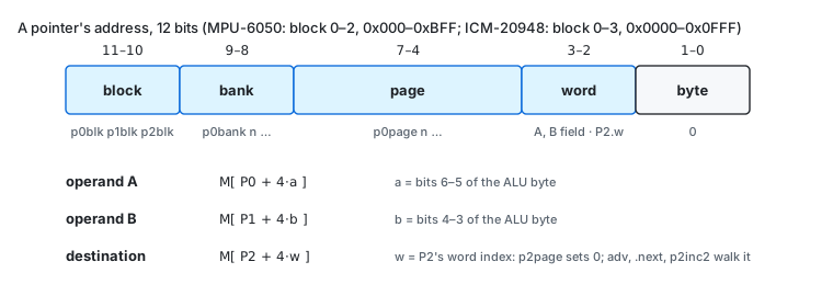
Figure 2-3. How an operand address is formed
Each pointer holds three fields, each set by its own instruction:
address = block * 1024 + bank * 256 + page * 16 block 0-3, bank 0-3, page 0-15
| Field | Set by | Notes |
|---|---|---|
| block | p0blk, p1blk, p2blk |
Adds one block. MPU-6050: modulo 3, kept from pass to pass until DMP_RST. ICM-20948: modulo 4, cleared at the start of every pass. |
| bank | p0bank n, p1bank n, p2bank n |
|
| page | p0page n, p1page n, p2page n |
p2page also sets P2.w to 0. |
A page is four words, and the word within the page comes from a different place for each role:
| Operand | Address |
|---|---|
| A | M[P0 + 4·a], with a from bits 6–5 of the ALU byte |
| B | M[P1 + 4·b], with b from bits 4–3 of the ALU byte |
| MOV source | M[P0 + 4·k], with k from bits 2–1 of the MOV byte |
| destination | M[P2 + 4·P2.w] |
The destination word index. P2.w is a 2-bit counter that wraps from 3 to 0:
p2pagesets it to 0;- the advancing forms (
add A,B,inc,mov k,inc,clr.next,inc.next,dec.next,lo.next, a shift withadv) add 1 before they store; p2inc2adds 2.
The operand words are addressed directly; the destination is walked.
Persistence. Pointer loads are sticky. On the MPU-6050 every pointer field, and P2.w, carries from one pass to the next. On the ICM-20948 all three pointers and P2.w restart at 0x0000, word 0, at the start of every pass. After DMP_RST all three pointers are 0x000, word 0, on both cores.
On the MPU-6050, moving the destination clears R. Every instruction that changes P2 or P2.w on
the MPU-6050 also sets the result register R to 0: a P2 page or bank load, p2inc2, clr.next,
and every advancing form (§3.2).
There is no indexed or indirect addressing. Every address a program uses is fixed in its code.
2.6 Addressing Modes
| Mode | Instructions | Operand |
|---|---|---|
| Word-indexed | ALU operand A, MOV/MOVX source | M[P0 + 4·field] |
| Word-indexed | ALU operand B | M[P1 + 4·field] |
| Walked destination | every store | M[P2 + 4·P2.w], through the route |
| Route | every store | memory at P2 (store) or the FIFO (fifo) |
| Immediate | branch, jump, call, cmp.eq/gt/lt/ne, shl, sar |
a displacement, a 14-bit address, a 6-bit constant, a shift count |
| Register I/O (DMP3) | page loads in mode 4 | host register a / 4 |
The ALU has no other immediate operand. Every constant is a word in data memory (§2.7).
2.7 Data Types
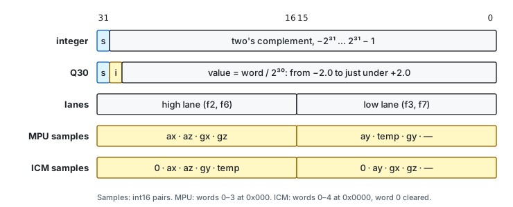
Figure 2-4. Word formats
Integer and Q30
A word is 32 bits, big-endian. The same bits can be read in two ways:
| Reading | Value | Range | Resolution |
|---|---|---|---|
| Integer | the two’s-complement word | −2³¹ to 2³¹ − 1 | 1 |
| Q30 fixed point | word / 2³⁰ | −2.0 to 2.0 − 2⁻³⁰ | 2⁻³⁰ ≈ 9.3 × 10⁻¹⁰ |
| Word | Integer | Q30 |
|---|---|---|
| 0x40000000 | 1073741824 | +1.0 |
| 0x60000000 | 1610612736 | +1.5 |
| 0x20000000 | 536870912 | +0.5 |
| 0x00000001 | 1 | 2⁻³⁰ |
| 0xE0000000 | −536870912 | −0.5 |
| 0x80000000 | −2147483648 | −2.0 |
The ALU does not know which reading a program intends:
- Same bits either way: ADD, RSUB, INC, DEC, CLR, MOV, MOVX, AND, XOR, CLAMP and every comparison. A program may use any word as a counter, a set of flags or a fraction.
- The one exception is multiplication. MUL, NMUL and MAC keep the product’s high bits: ⌊A·B / 2³⁰⌋. That is the right result for two Q30 operands, and for two integers it is their product divided by 2³⁰ (3 × 5 gives 0). §3.2 lists the ways to multiply integers.
Results wrap. A result that does not fit in the word (or the lane) is stored modulo 2³² (or 2¹⁶); nothing saturates. The flag F still sees the exact result: in Q30, 1.0 + 1.5 stores −1.5 and leaves F clear.
Lanes
Under the lane modes the ALU computes on one 16-bit half of each word (Figure 2-4):
| Mode | Lane | Operands | Result |
|---|---|---|---|
fmode 2, fmode 6 |
high | the high half-words, in place (the low halves read as 0) | writes the high half; the low half is unchanged |
fmode 3, fmode 7 |
low | the low half-words, sign-extended, as integers | writes the low half; the high half is unchanged |
A lane result routed to the FIFO is 2 bytes. There is no carry between the halves. The lanes are true 16-bit integer ALUs for add, subtract, increment, decrement, clear, AND, XOR and CLAMP.
Samples as values
A sample is a 16-bit count in one half of a word (§2.4). Two conversions are common:
- Moved into the high half of a cleared word (
clr, thenmovormovxunderfmode 2), a count c reads in Q30 as c / 16384. - Kept in the low half, it is an integer under
fmode 3.
Constants
There is no constant memory and no immediate data operand. The host writes every constant the
program reads, including the 0.0 that a copy or an emit adds, into data memory before it starts
the DMP. In assembly, .dw places them (Chapter 8):
        .chip   mpu6050
        .org    0x100
k:      .dw     0.5q, 1.5q, 100i, 0x7fff     ; Q30 0.5, Q30 1.5, the integer 100, a hex word
        .org    0x400
        fmode   1
        always
        end
        ; expect 0x100 = 20000000, 60000000, 00000064, 00007fff
2.8 Allocating Storage
There is no allocator. A program owns every byte outside the sample page, the FIFO and its own code.
- Group data in pages of four words. An ALU instruction reaches all four words of each operand page without a pointer reload, and the destination walks the four words of its page.
- Recommended layout.
- MPU-6050: data from 0x010 to 0x3FF, code from 0x400.
- ICM-20948: data from 0x0020 to 0x0FFF (the sample page reaches 0x0011), code from 0x1000, everything below 0x3000.
- Data beyond block 0 (MPU 0x400–0xBFF, ICM blocks 1–3) is reached with
p0blk,p1blkorp2blk. On the MPU-6050 the block field persists across passes, so a pass that moves a block must move it back: threepNblkin all. - Initial values. The host writes initial values after the device reset and before it enables the DMP.